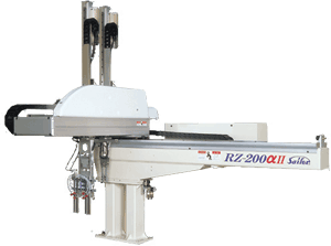
Sailor – RZ-αⅡ Series
Posted by: Eastern Plastics | on June 7, 2013


| Compact body with Sailor Technology
For 75-350 ton Molding Machine Application |

| Take-out dry cycle |
below 1.0 sec. |
| Overall dry cycle |
below 6.0 sec. |
|
|
| ■Introduce product and functions |
|
3 or 5 Axis Full Servo Automatic Extraction Robots.
Advanced function [vibration suppressing control] and so on, all machine equipped new idea and new technology. |
Vibration Free…Advanced function
[Vibration Suppressing Control]
|
|
Reduce the arm vibration by 1/10th(*) delivers more accurate and speedy take-out.
(in-house comparison) |
Small and Light Weight
[Handy Touch Panel]
|
|
This plastic operation panel can be a hand-held pendant…..easy to operate by a hand. Japanese, English and Chinese languages are available. |
Reliable and Durable
[Rack and Pinion Mechanism] |
|
The vertical and traverse adopt a reliable and durable rack and pinion mechanism.
(except telescopic type) |
|
 |
| Power Supply |
AC200V±10% 50/60Hz |
| Max electric power required |
4kVA |
| Normal air pressure |
0.5~0.6MPa |
| Max air pressure capacity |
0.97MPa |
| Max loading capacity |
8kg(including chuck unit) |
| Accuracy of re-positioning |
±0.1mm |
|
| Model |
Vertical
guide |
Arm |
Molding
machine
application |
Movable Range |
Weight
(Standard Spec)
[kg] |
Vertical
stroke
max[mm] |
Traverse
stroke
max[mm] |
Horizontal
stroke max[mm] |
Part
-side |
Runner
-side |
| RZ-100αⅡ |
Standard |
S |
75~120t |
700 |
1200 |
360 |
300 |
| W |
370 |
230 |
320 |
| Telescopic |
S |
360 |
315 |
| W |
355 |
230 |
350 |
| RZ-200αⅡ |
Standard |
S |
150~250t |
800 |
1400 |
490 |
320 |
| W |
400 |
230 |
340 |
| Telescopic |
S |
490 |
335 |
| W |
385 |
230 |
370 |
| RZ-300αⅡ |
Standard |
S |
250~350t |
1000 |
1600 |
690 |
410 |
| W |
600 |
280 |
440 |
| Telescopic |
S |
690 |
425 |
| W |
585 |
280 |
470 |
| S: Single arm |
W: Double arms |
|
|
Standard specification
| 1 |
A-type 90 degree Wrist turn unit |
| 2 |
Parts vacuum Circuit, Detect Circuit |
| 3 |
Mechanical parts Chuck Circuit |
| 4 |
Wrist Turn Sequence Control |
| 5 |
Parts & Runner Ejection Positions |
| 6 |
Pirority Setting for Parts or Runner Ejection |
| 7 |
Parts & Runner Vertical Position Ejection Setting |
| 8 |
Definable Runner Release Position (before or after parts unload) |
| 9 |
All Axis Parts Palletizing (999 positons for each axis) |
| 10 |
Definable Palletizing Direction for Kick and Traverse strokes |
| 11 |
Definable Shift Position and Direction for Kick and Traverse strokes |
| 12 |
Intermediate Traverse Wait Positioning |
| 13 |
Teaching Data Verification Check Function |
| 14 |
Data Protection Function (Password) |
| 15 |
Clock Setting and display Function |
| 16 |
Initial Reject, NG Parts Reject, Overflow Reject |
| 17 |
Molding Shutdown Mode after Consecutive NG Signals |
| 18 |
Definable Auxiliary Machine Interlock |
| 19 |
Proximity to Mold Halt – Vertical Axis |
| 20 |
Curved Approach on Mold Movement |
| 21 |
Alarm History Report |
| 22 |
Set Robot Maintenance Records/ Requiremants w/Alarm Notice |
| 23 |
Teach Positioning on the Fly in Full Auto Mode (max. ±3.00mm) |
| 24 |
Power Save Operation |
| 25 |
Sampling Mode |
| 26 |
Production Control Mode |
Optional Specifications
| 1 |
AB & D-type Wrist Turn Unit |
| 2 |
Vacuum dual system circuit increased capacity for large product |
| 3 |
Vacuum Circuit for Parts Side Runner |
| 4 |
Pivot Wrist Turn Sequence Control |
| 5 |
2Position for Parts Unload |
| 6 |
Traverse End Gate-cut 4 positions/cycle |
| 7 |
Traverse End Gate-cut Direction Setting for all axis |
| 8 |
Inside Chuck Gate-cut Unload or Midway Position |
| 9 |
Chuck Pitch Adjustment |
| 10 |
Air Movement of Undercut Remove |
| 11 |
Alarm Lamp |
| 12 |
Vacuum Multiple-System Circuit (over 3 systems) |
| 13 |
Blower specification |
| 14 |
Vacuum Break Circuit |
Posted in | Comments Off on Sailor – RZ-αⅡ Series


 D5 Creation